I’ve written about zones and boundaries before. Since then, the data structs behind zones have changed a bit. Also, I didn’t cover zones with holes. The old post is still relevant and there’s a bunch I won’t repeat here.
In this post, I talk about zones with holes and with multiple boundaries. Multiple boundaries makes it easier to move the zones together as a unit.
The code associated with this post is here.
Here’s a video talking mostly about the steps needed in inkscape to draw the graphic. Also has scripting details, but the text below is probably more informative:
Zone basics, revisited
pcbnew zones are stored in ZONE_CONTAINERs. They are what you get when you call board.InsertArea to create a new zone. Something like this:
[code]
SCALE = 1000000.0
zone_container = board.InsertArea(powernet.GetNet(), 0, powerlayer,
int(10*SCALE), int(10*SCALE),
pcbnew.CPolyLine.DIAGONAL_EDGE)
[/code]
That creates a single point zone on net powernet and layerpowernet1
To modify the zone, you need to access the shape_poly_set. It’s a single data struct that holds all of the coordinates.
[code]
shape_poly_set = zone_container.Outline()
[/code]
To add points:
[code]
shape_poly_set.Append(int(10*SCALE), int(20*SCALE))
[/code]
But there are some details hidden there. Append actually takes a bunch more arguments. From the c++ code:
[code]
/**
* Function Append
* adds a new vertex to the contour indexed by \p aOutline and \p aHole (defaults to the
* outline of the last polygon).
* @param x is the x coordinate of the new vertex.
* @param y is the y coordinate of the new vertex.
* @param aOutline is the index of the polygon.
* @param aHole is the index of the hole (-1 for the main outline),
* @param aAllowDuplication is a flag to indicate whether it is allowed to add this
* corner even if it is duplicated.
* @return int – the number of corners of the selected contour after the addition.
*/
int Append( int x, int y, int aOutline = -1, int aHole = -1,
bool aAllowDuplication = false );
[/code]
aOutline tells which boundary you want to add to. By default, you add to the last one -1. If aHole is -1, you’re telling it you want the bound, not a hole. You see, the boundaries/outlines are numbered 0+. Same with the holes.
so, with the single outline zone we’re messing with now, the call above is equivalent to these:
[code]
shape_poly_set.Append(int(10*SCALE), int(20*SCALE))
shape_poly_set.Append(int(10*SCALE), int(20*SCALE), -1)
shape_poly_set.Append(int(10*SCALE), int(20*SCALE), 0)
[/code]
One last thing, you’ll probably want this line, to make the edges more visible:
[code]
zone_container.Hatch()
[/code]
Additional outlines
It can be helpful to have multiple outlines on the same zone. That way, moving one moves the other. Unlike the initial zone method, InsertArea, this time all of the points are added with Append
You’ll need code like this:
[code]
shapeid = shape_poly_set.NewOutline()
shape_poly_set.Append(int(10*SCALE), int(20*SCALE), shapeid)
[/code]
Adding holes
Adding holes is similar to adding outlines. Note that you are adding a hole to a particular outline:
[code]
hi = shape_poly_set.NewHole()
shape_poly_set.Append(int(10*SCALE), int(20*SCALE), -1, hi)
shape_poly_set.Append(int(10*SCALE), int(20*SCALE), outlineid, hi)
[/code]
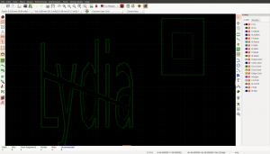
Putting it together with an SVG
So, I wanted to convert an inkscape drawing into a zone. I have a post on my other blog talking about how to parse SVG paths. The code for the parse I wrote is here. I also have a blog post one understanding and parsing svg. The main function returns instances of a class I called SVGpath, which will give you a list of polys and holes. I have a helper function to group the bounds with their holes. The result is this code for creating my zones:
[code]
# here I load from drawing.svg in the current directory. You’ll want to change that path.
paths = parse_svg_path.parse_svg_path(os.path.dirname(inspect.stack()[0][1]) + ‘/drawing.svg’)
if not paths:
raise ValueError(‘wasnt able to read any paths from file’)
# things are a little tricky below, because the first boundary has
# its first point passed into the creation of the new area. subsequent
# bounds are not done that way.
zone_container = None
shape_poly_set = None
for path in paths:
for shape in path.group_by_bound_and_holes():
shapeid = None
if not shape_poly_set:
# the call to GetNet() gets the netcode, an integer.
zone_container = board.InsertArea(powernet.GetNet(), 0, powerlayer,
int(shape.bound[0][0]*SCALE),
int(shape.bound[0][1]*SCALE),
pcbnew.CPolyLine.DIAGONAL_EDGE)
shape_poly_set = zone_container.Outline()
shapeid = 0
else:
shapeid = shape_poly_set.NewOutline()
shape_poly_set.Append(int(shape.bound[0][0]*SCALE),
int(shape.bound[0][1]*SCALE),
shapeid)
for pt in shape.bound[1:]:
shape_poly_set.Append(int(pt[0]*SCALE), int(pt[1]*SCALE))
for hole in shape.holes:
hi = shape_poly_set.NewHole()
# -1 to the third arg maintains the default behavior of
# using the last outline.
for pt in hole:
shape_poly_set.Append(int(pt[0]*SCALE), int(pt[1]*SCALE), -1, hi)
zone_container.Hatch()
[/code]